


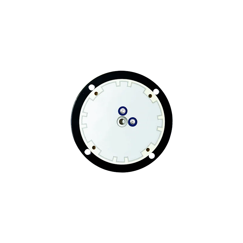
Choosing the right Internal Antenna is one of the most consequential RF decisions in any compact IoT or wearable product. The wrong choice can quietly degrade GNSS fix rate by 30 to 50 percent, drain battery life, and force a costly mechanical redesign late in the program. This guide walks through what an internal antenna actually does, the specifications that matter, and the practical trade-offs we have learned while shipping millions of integrated antenna modules into connected asset trackers, fitness bands, livestock tags, and industrial sensor fleets.
If you are a hardware engineer, a system architect, or a product manager about to spec a compact GNSS product for the first time, the goal of this article is to give you a framework that survives the transition from datasheet to mass production. We will not focus on any single chipset, and we will not push a one-size-fits-all answer, because no internal antenna solution is universal. What is universal is the evaluation discipline.
What Is an Internal Antenna?
An internal antenna is a radiating element fully enclosed inside a product enclosure. There is no SMA connector, no external whip, and no exposed patch on the housing. For GNSS applications, an internal antenna is typically a ceramic patch, a flex PCB (FPCA), a stamped metal antenna, or a Laser Direct Structuring (LDS) design printed directly onto a plastic carrier.
The defining trait is that the antenna shares its RF environment with the rest of the device: the battery, the display, the user's hand, and the enclosure walls. That co-existence is exactly what makes internal antenna selection more nuanced than plugging in a known-good external antenna. The antenna is no longer isolated from the product; it is part of the product.
Why Internal Antennas Matter for IoT and Wearable Designs
External antennas give you a known baseline. Internal antennas, by contrast, require the OEM to take responsibility for the entire RF chain, from the antenna element and the ground plane, to the matching network, the enclosure, and the use-case geometry. A few percentage points of efficiency lost in any one of these areas show up directly as longer time-to-first-fix (TTFF), more dropped fixes in weak-signal environments, and worse performance when the device is worn on a wrist or attached to a metal asset.
For high-volume consumer wearables, internal antennas also unlock the mechanical simplicity that makes a product manufacturable in the first place. There is no antenna port on the enclosure, no field-replaceable whip, and no IP rating compromise from an external feedthrough. The internal antenna is what makes a sleek, sealed, factory-only device possible, and it is also what makes the product succeed or fail in the field.
Key Specifications to Evaluate Before You Commit
When we review an internal antenna candidate for a customer program, the same five specifications decide whether the part moves forward. Skim them in this order; the later items only matter once the earlier ones are acceptable.
1. Frequency band and constellation coverage. GPS L1 at 1575.42 MHz is no longer the only game in town. If your product needs BeiDou B1, Galileo E1, GLONASS L1, or the modern L5 and E5a band for ionospheric robustness, the antenna must be designed for that center frequency with adequate bandwidth. A GPS-only L1 antenna will technically see other L1 signals, but its tuning will be off-center and your real-world gain will suffer.
2. Efficiency, not just peak gain. Antenna vendors love to print the peak gain number on the front page. In our experience, total radiated efficiency (typically 40 to 70 percent for a well-tuned internal antenna) is what correlates with real-world GNSS performance. A 3 dBi peak gain antenna at 30 percent efficiency will underperform a 1 dBi peak gain antenna at 65 percent efficiency in almost every customer scenario we have measured.
3. VSWR across the operating band. A VSWR of 1.5 to 1 is the threshold below which the matching network can be simple. Above 2 to 1 you are likely looking at a multi-component LC network, a chip inductor, or a tunable matching IC, all of which add BOM cost and consume board space that an IoT product rarely has.
4. Polarization behavior. GNSS signals are right-hand circularly polarized (RHCP). A linear-polarized internal antenna trades 3 dB of free-space gain for cheaper construction. The trade is acceptable for many tracking use cases but unacceptable for wearables that need to lock on quickly with the device held at an arbitrary angle against the body.
5. Ground plane dependence. Almost every internal antenna vendor publishes a reference efficiency measured on a 50 mm by 50 mm ground plane. If your product PCB is smaller, larger, or a different shape, the published number is decorative. Always ask for efficiency versus ground-plane-size data, or plan to do a tune on your own board.
How to Match the Antenna to Your Device Form Factor
The mechanical envelope of the product usually narrows the antenna choice before the electrical specs even come into play. Three form factors dominate our customer portfolio, and each of them stresses a different part of the design.
Wearable bands and patches. A 25 mm by 25 mm ceramic patch, or a 20 mm by 8 mm flex FPCA, fits on a flexible wristband and keeps the user-facing side flush. The trade-off is that the antenna is close to the body, which can knock 5 to 10 dB off the link budget. RHCP and a well-designed ground plane are non-negotiable here.
Compact asset trackers. For OBD-style and pallet trackers, an internal patch with a metal shield can be tuned for the GPS L1 and L5 bands simultaneously. The housing is usually large enough (60 mm by 40 mm or bigger) that the ground plane is generous, and efficiency above 60 percent is achievable with stock parts.
Sensor and meter modules. Industrial sensors, including water meters, gas meters, livestock ear tags, and agricultural probes, often put the antenna next to a coin cell, a metal bracket, or a concrete wall. In this environment, a directional or pattern-diverse antenna design with two orthogonal elements fed through a combiner outperforms a single patch by 8 to 12 dB in our field measurements.
Common Integration Pitfalls and How to Avoid Them
Most internal antenna problems we diagnose in the lab trace back to one of three root causes. The good news is that all three are visible during the EVT phase if you know what to look for.
Pitfall 1: a battery or display sitting on top of the antenna. The radiating element needs a clear hemisphere toward the sky. A 3 mm clearance above the antenna, kept free of metal and high-permittivity materials, usually recovers 4 to 6 dB that would otherwise be lost.
Pitfall 2: a ground plane split by a slot or a routing channel. A long, thin PCB ground can detune the antenna by 20 MHz or more. If you must route signals across the ground, use vias to stitch both sides of the ground and keep the antenna's keep-out area free of high-speed traces.
Pitfall 3: forgetting the enclosure. A plastic enclosure with a high ceramic filler content can shift the antenna's center frequency by 5 to 10 MHz. Tune the antenna after the final enclosure is selected, not before. We have rescued more than one program by adding a single shunt capacitor to the matching network after the customer locked in the housing tooling.
Where We Fit: xyzgnss Internal Antenna Solutions
At xyzgnss we have spent more than a decade building GNSS modules, antennas, and receivers for the industrial and wearable markets. Our internal antenna portfolio is engineered for the realities our customers face: small ground planes, sealed enclosures, body-worn devices, and tight BOM targets. We ship the antenna, the matching network reference design, and the layout guidelines together, so a customer can move from a working EVT to a production-ready design without re-tuning the entire RF chain.
Our internal antenna family covers passive ceramic patches, FPCA flex antennas, and integrated antenna-module combinations. For developers looking for a single-part solution, our GPS module with integrated antenna combines the front-end, the receiver IC, and the antenna on one carrier, removing the matching network from the customer's design entirely. For compact IoT nodes, the antenna-integrated GNSS module in our YM series ships in a 10 mm by 10 mm footprint and is qualified on a 30 mm by 30 mm ground plane reference design.
Customers also use our existing field-tested notes on internal antenna performance optimization and our industrial sensor integration guide as engineering references during the bring-up phase. If you would like a sample of any of our internal antenna parts, our technical team can ship an evaluation kit with a matched reference board, an active LNA, and a test report within two business days.
Conclusion
An internal antenna is never just a part number on a BOM. It is a system decision that ties the RF performance, the mechanical design, the battery budget, and the manufacturability of your product together. If you are starting a new IoT or wearable program and want a sanity check on your antenna selection before you commit to tooling, our RF engineering team is happy to review your stack-up and your enclosure constraints and recommend a starting point from our internal antenna family.
Ready to evaluate an internal antenna for your next IoT or wearable design? Talk to our RF engineering team about a sample kit, a layout review, or a custom internal antenna design. Contact xyzgnss to start a project →
Frequently Asked Questions
Q1: What Is an Internal Antenna and How Does It Differ From an External Antenna?
An internal antenna is fully enclosed inside the device housing, with no external radiating element or connector. An external antenna protrudes from the enclosure via an SMA or similar port. Internal antennas trade some peak gain and efficiency for a sealed, mechanically simpler product, while external antennas give a more predictable RF baseline at the cost of an external feature on the housing.
Q2: Can an internal antenna work for multi-constellation GNSS, including BeiDou and Galileo?
Yes, provided the antenna is designed for the relevant center frequency and bandwidth. Most modern internal antenna parts cover GPS L1, BeiDou B1, Galileo E1, and GLONASS L1 simultaneously because all four constellations share the same 1559 to 1606 MHz band. For L5 or E5a robustness, you need an internal antenna explicitly designed and tested at the higher band, not a single-band L1 part retuned by a matching network.
Q3: How small can an effective internal antenna be for a wearable device?
A passive ceramic internal antenna can deliver usable efficiency down to about 10 mm by 10 mm. Below that size, an active internal antenna with a low-noise front-end, or an integrated antenna-module, becomes the realistic path. Performance depends heavily on the ground plane and the enclosure, and a wearable-sized internal antenna almost always needs a tuning pass against the final housing.
Q4: Do I need to retune an internal antenna when I change the enclosure?
In most cases, yes. Plastic enclosure materials, especially those with high ceramic or glass filler content, shift the internal antenna center frequency by 5 to 10 MHz. We recommend building the matching network with a small tunable element, or budgeting a single re-spin of the matching components after the final housing is selected.
Q5: Where can I get an evaluation kit to test an internal antenna with my hardware?
We provide evaluation kits for every internal antenna in our portfolio. A standard kit includes the internal antenna on a reference board, a matched LNA, a USB interface for raw GNSS output, and a test report covering efficiency and radiation pattern on multiple ground-plane sizes. Contact our engineering team and we can typically ship a kit within two business days.