


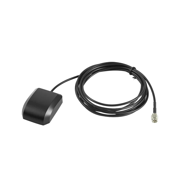
Selecting a GPS antenna is the single RF decision that quietly determines whether a GNSS product works in the field. The right GPS antenna gives a clean satellite lock in seconds and holds it under canopy, in urban canyon, and at the edge of a constellation. The wrong one looks fine on the bench and falls apart the moment the device leaves the parking lot. This guide walks through what a GPS antenna actually does, the specifications that drive its real-world behavior, and the design choices that separate a benign-environment part from a GPS antenna that has to work in a hostile one.
If you are a hardware engineer, a system architect, or a product manager about to spec a GPS antenna for the first time, the goal of this article is to give you a working framework that survives the transition from a datasheet to a deployed product. We will not push a single antenna topology, because no GPS antenna fits every application. What we will do is walk through the criteria that actually matter when the box is on the bench and the device is in the customer's hand.
What a GPS Antenna Actually Does
A GPS antenna converts the free-space GNSS signal at 1575.42 MHz into a guided signal on a coax or a PCB trace, with enough gain and the right polarization to allow the receiver to track the satellite. For L1, a GPS antenna is typically a patch, a quad-helix, a turnstile, or a small chip antenna; for L1 plus L5, the same topologies are used with wider-band materials. The defining trait of a serious GPS antenna is that the gain pattern peaks toward the sky and rejects energy arriving from below the horizon.
In practice, the GPS antenna also acts as a filter for the rest of the system. The polarization purity of the GPS antenna sets the multipath rejection of the receiver; the out-of-band rejection of the GPS antenna sets the interference immunity of the receiver; the phase-center stability of the GPS antenna sets the positioning accuracy of the receiver. None of these are visible from a peak-gain number on a datasheet, but all of them show up in field performance.
Why the GPS Antenna Choice Drives Everything Downstream
A GPS antenna is not just a passive component. It is the first stage of the RF chain, and every stage after it inherits the choices made at the antenna. Three downstream effects dominate.
Time to first fix. A GPS antenna with high efficiency and a clean polarization delivers a usable signal-to-noise ratio in 5 to 10 seconds, even in moderate canopy. A GPS antenna with poor efficiency forces the receiver to integrate longer, which adds seconds or minutes to the time-to-first-fix and degrades the user experience.
Fix retention. A GPS antenna that rejects multipath will hold a fix under tree canopy, in urban canyon, and on a dashboard. A GPS antenna that lets multipath through will see the position jump around by tens of meters in exactly the environments the customer cares about most.
Interference immunity. A GPS antenna with a sharp bandpass filter in front of the LNA will reject the out-of-band cellular and radar signals that would otherwise saturate the front-end. A GPS antenna with no filtering forces the receiver to track in a noisier environment, which costs fix rate and time-to-first-fix.
Reading a GPS Antenna Datasheet Without Being Misled
Reading a GPS antenna datasheet without a framework is a recipe for buying the wrong part. The following six specifications decide whether a GPS antenna is right for your program.
1. Frequency band and bandwidth. A modern GPS antenna should cover at least the 1559 to 1606 MHz band, which encompasses GPS L1, BeiDou B1, Galileo E1, and GLONASS L1. A part that only covers a narrow band at L1 will technically work, but the off-center tuning will cost you 1 to 2 dB of gain on the other constellations. For L5 and E5a robustness, you need a wider-band GPS antenna explicitly designed for the higher band.
2. Total radiated efficiency. A GPS antenna with 60 to 70 percent efficiency is the practical sweet spot for most OEM products. A part that publishes only peak gain (in dBic or dBi) is hiding the number that actually matters. Always ask for the efficiency vs. frequency curve, and check it on a ground plane size that matches your product.
3. Polarization purity. A GPS antenna with an axial ratio below 3 dB at the zenith preserves the RHCP of the GNSS signal and rejects the cross-polarized multipath. A GPS antenna with a 6 to 10 dB axial ratio trades polarization purity for cheaper construction, and the trade shows up as worse multipath rejection in the field.
4. VSWR across the operating band. A GPS antenna with VSWR below 1.5 to 1 across the band needs only a simple matching network. Above 2 to 1, the matching network starts to consume board space and BOM cost. A GPS antenna with VSWR above 3 to 1 is not usable without an active matching stage.
5. Out-of-band rejection. A GPS antenna with a SAW filter in front of the LNA will reject the cellular, radar, and satellite-DAB energy that lives just outside the GNSS band. A GPS antenna with no filtering will see that out-of-band energy fold into the LNA and saturate the front-end, which costs fix rate and time-to-first-fix.
6. Ground plane dependence. A GPS antenna published with 70 percent efficiency on a 50 mm ground plane may drop to 40 percent on a 30 mm ground plane, or fall to 20 percent on a long thin ground. Always check the efficiency curve across the ground plane sizes you actually plan to use, or budget a custom tune on your own board.
How to Match a GPS Antenna to Your Environment
A GPS antenna is only as good as the environment it has to work in. Three environments dominate the GPS antenna deployments we ship, and each one stresses a different part of the design.
Open sky. Open-sky applications like surveying, marine navigation, and agricultural machinery are the easiest environment for a GPS antenna. A wide-band patch with 60 percent efficiency and a clean polarization will deliver the 1 to 2 m accuracy the customer expects. The main risk is multipath from a metallic vehicle roof or a wet crop canopy, which a high-rejection GPS antenna handles better than a generic part.
Tree canopy. Under tree canopy, the GPS antenna sees attenuated and multipath-corrupted signals. A high-axial-ratio GPS antenna with strong multipath rejection outperforms a generic patch by 3 to 5 dB, which is the difference between holding a fix and losing it. For forest and orchard applications, the GPS antenna is the single most leveraged part of the BOM.
Urban canyon. In urban canyon, the GPS antenna has to reject the strong reflections from buildings, work through attenuated line-of-sight signals, and tolerate the interference from nearby cellular base stations. A high-rejection GPS antenna with sharp out-of-band filtering and good axial ratio is the only practical answer. A generic patch will lose lock every time the user turns a corner.
Common Pitfalls in GPS Antenna Integration
Across our GPS antenna deployments, the same four mistakes show up more often than the others. Skim them before you commit to a BOM.
Mounting the GPS antenna on a metal ground plane that is too small. A GPS antenna that needs a 50 mm ground plane and gets a 25 mm ground plane will lose 5 to 10 dB of efficiency. Either pick a smaller GPS antenna, or extend the ground plane under the antenna with a tab.
Forgetting the enclosure. A plastic enclosure with a high ceramic filler content can shift the GPS antenna's center frequency by 5 to 10 MHz. Tune the matching network after the final enclosure is selected, not before. We have rescued more than one program by adding a single shunt capacitor after the customer locked in the housing tooling.
Routing noisy traces across the antenna feed. A high-speed digital trace routed across the GPS antenna feed will couple noise into the LNA. Use vias to stitch both sides of the ground and keep the antenna keep-out area free of high-speed traces.
Picking the cheapest GPS antenna. A GPS antenna that is 30 percent cheaper than the next option is almost always using a cheaper ceramic or a less tightly toleranced LNA. The cost shows up in the field as lower fix rate, longer time-to-first-fix, and more customer support tickets. A serious GPS antenna is an investment, not an expense.
Where We Fit: xyzgnss GPS Antenna Portfolio
At xyzgnss we have spent more than a decade building GPS antennas, GNSS modules, and receivers for industrial, surveying, and OEM customers. Our GPS antenna portfolio is engineered for the realities our customers face: small ground planes, sealed enclosures, body-worn devices, and tight BOM targets. We ship the GPS antenna, the matching network reference design, and the layout guidelines together, so a customer can move from a working EVT to a production-ready design without re-tuning the RF chain.
You can browse the GPS antenna family on the product page, and read our engineering notes on optimizing GNSS performance with a high-precision GPS antenna for a wider view of the trade-offs. For a hands-on reference, the all-antenna product page lists our wider portfolio, and our GPS antenna YH-5361 is a representative high-axial-ratio patch for demanding applications.
If you are evaluating a GPS antenna for a new program, our technical team can ship an evaluation kit with a matched reference board, an active LNA, and a test report within two business days. We have supported surveying, agricultural, marine, and OEM customers across multiple regions, and we are happy to bring that field experience to your project.
Conclusion
A GPS antenna is the most leveraged passive component in any GNSS product, and the choice of topology, gain pattern, and frequency band drives the rest of the RF chain. If you are weighing a new GPS antenna for a survey, agricultural, marine, or OEM program, our engineering team can help you compare the candidates in your real environment before you commit to a BOM.
Need help selecting a GPS antenna for your application? Talk to our engineering team about an evaluation kit, a layout review, and a reference design for your environment. Contact xyzgnss to start a project →
Frequently Asked Questions
Q1: What Is a GPS Antenna and How Does It Differ From a GNSS Antenna?
A GPS antenna is an antenna designed to receive the GPS L1 signal at 1575.42 MHz, often with the option to cover the broader L1 band shared by GPS, BeiDou, Galileo, and GLONASS. A GNSS antenna is a wider-band antenna designed to receive all four constellations simultaneously. In practice, the two terms are often used interchangeably, and a serious GPS antenna will cover the full 1559 to 1606 MHz band by default.
Q2: How Important Is Axial Ratio for a GPS Antenna?
Axial ratio is the single most important specification for a GPS antenna that has to work under tree canopy or in urban canyon. A GPS antenna with an axial ratio below 3 dB at the zenith preserves the RHCP of the GNSS signal and rejects cross-polarized multipath. A GPS antenna with a 6 to 10 dB axial ratio trades polarization purity for cheaper construction, and the trade shows up as worse multipath rejection in the field.
Q3: Do I Need an Active or a Passive GPS Antenna?
An active GPS antenna has an LNA built into the antenna housing and is the right choice for any application where the coax run is longer than 1 to 2 meters, or where the receiver is not adjacent to the antenna. A passive GPS antenna is the right choice for very short coax runs and for cost-sensitive applications where the BOM savings outweigh the link budget. For most OEM products, an active GPS antenna is the safer default.
Q4: Can a GPS Antenna Reject Cellular Interference?
A GPS antenna with a SAW filter in front of the LNA can reject the out-of-band cellular, radar, and satellite-DAB energy that lives just outside the GNSS band. A GPS antenna with no filtering will see that out-of-band energy fold into the LNA and saturate the front-end, which costs fix rate and time-to-first-fix. For any deployment near a cellular base station, a filtered GPS antenna is worth the small BOM premium.
Q5: Where Can I Get an Evaluation Kit to Test a GPS Antenna With My Hardware?
We provide evaluation kits for every GPS antenna in our portfolio. A standard kit includes the GPS antenna on a reference board, a matched LNA, a USB interface for raw GNSS output, and a test report covering efficiency, axial ratio, and radiation pattern on multiple ground-plane sizes. Contact our engineering team and we can typically ship a kit within two business days.